This time I want to stop with very complicated dynamo scripts and workflows just because sometimes basics are important as well.
In this article I'll focus on the procedure to setup a common shared coordinate environment useful both as internal, if you manage multiple disciplines in your company, and external if you have to deal with consultants.
As always, I'll try to use as much as possible, screenshots from the software.
The first step is to create a new project with grids and levels. You can start from your template or just from a blank default template.

If you choose for the second option go directly to the "Site" view to be able to see the "Project Base Point". This will be the "Origin" of your project and the reference for all the other linked models.

If you're not able to see this element, just open the Visibility Graphics window (VV) and make visible the element under "Site" category

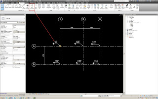
Now it's time to create grids and level according the structural alignments. I suggest to create levels according to the FFL level (finish floor level) because this will be the level used by surveyors to mark elevations on site.

Always for the surveyors team, place dimensions between grids and, most important place coordinates at each intersections (they'll come hundred of times to ask for these). Before starting with coordinates, of course you've to setup the real coordinates of the project base point. To do this, select the point and fill the correct information for N, E, Elevation and angle with north direction. For this example I'll just change angle and elevation


Now you can place coordinates at each intersection and then we can move to an elevation view to create levels


Now you reference model is ready to be shared with other stakeholder. Just save this file and open a new file.

As example I'll use a Mechanical template just to show the process that can be used with any template.
Create a new link and choose "Origin to Origin" as link method and choose the grid model created.


I suggest to select the link and Pin the model in order to prevent that the model is moved by someone accidentally

The project base point of the discipline model is still in 0,0 origin as you can see from the screenshot

Now we have to "Acquire" the shared coordinate system from the linked file to match the two files locations.

Then you're prompted to select a link that contains the shared coordinate system

Now, if you select again the project base point, magically, the coordinates are correct. Easy!

Last but not least, we have to acquire also the grid locations and the levels from the model. Many times I noticed that users try to recreate manually the levels and the grids but this is not the correct procedure. To be able to track changes and to be sure that everything is aligned, we should use the "Copy Monitor" function.

Activate the tool and select the link.
Then follow the numbers on the screenshots to finalize the task. Basically you've to copy, activate multiple, select all the grids in the view and finally you've to finish twice the operation (in the correct order)


Now if you try to select a grid, you'll see an icon saying that the grid is monitored

And if you try to move the grid manually, you'll receive a coordination alert

This is amazing because you can always keep the grids updated and aligned with the project standard and, under coordination review, you can always check what is changed and accept or reject the change with a comment.

Now we have to do the same with levels in a elevation view.


Last operation is to create plan views for the related levels in order to start to work.


We can easily create all the views that we need selecting, at the same time, the appropriate view template

Now just to be sure that everything is correct we can draw a small piece of duct and save/close the model.

Open the grid model and link the duct model, this time by shared coordinates. the model is exactly where it should be and if you select the instance of linked file is showing the correct coordinate system

Now everything is matching, the surveyors are happy, engineers are happy, you as BIM Manager are happy and we can go to sleep :)
Enjoy
Thanks for the best content
ReplyDeleteGREAT WORK
Bim consulting Bangalore